
These are the steps for deployment of the Juniper vRR (virtual route reflector) on Proxmox VE. For those not unaware, the virtual route reflector gives you the full policy capability of JunOS for routes without the actual forwarding engine. The route reflectors can then be configured using existing configuration tools without having to build tooling for other options like . and without deploying
I prefer to use the vRR over other options such as FRR as existing configuration tools and skills can be used. If you already have Proxmox VE running you also don’t need to deploy any other hardware, and since its just a VM you are not tied to any specific hardware.
The real world resource usage of the VM is quite low; 2GB of RAM and a single vCPU is sufficient for a few logical systems each containing a full BGP table with ~10 BGP peers each. Since its a VM you can monitor the resource usage and adjust as needed for your specific situation.
Proxmox Setup
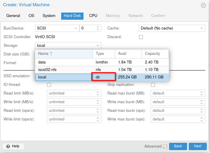
During the initial vRR deployment it is preferred to use a directory type storage target to store the disk images. After the vRR setup is complete the storage can be migrated to LVM if you need. By default, the Proxmox setup will create two storage pools (the NFS pool is added by me and will not be present on your install):
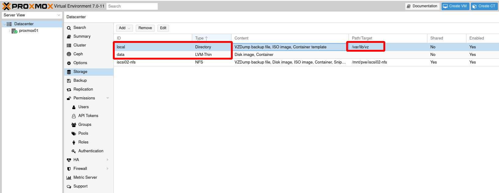
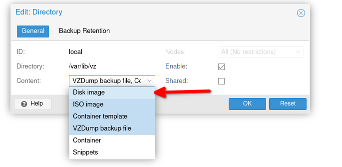
To allow the directory type storage target to store container images, edit the “local” ID and in the content section make sure the “disk image” option is selected:
Take note of the storage directory, the default is /var/lib/vz, this will be where the disk image for the VM is stored which is needed for later steps.
VM Creation
For the purposes of this guide, the VM will be configured with 2 interfaces. Interface 1 (em0) will be assigned VLAN tag 10 and interface 2 (em1) will be assigned VLAN tag 20.
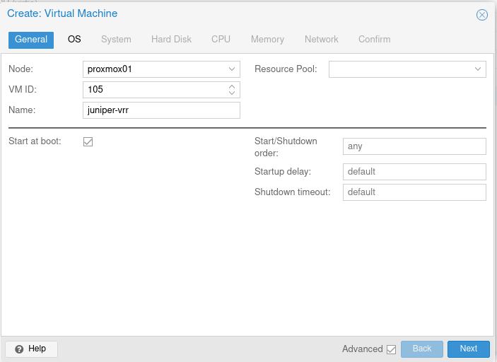
Start the VM creation process as normal. On the general screen nothing needs to be changed.
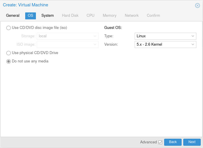
On the OS screen select the option for “Do not use any media”. The default Guest OS type can be left as the default.
On the System screen everything can be left as default. The “Qemu Agent” option should not be selected as that is not supported on the VM.

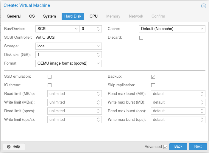
On the Hard Disk screen set the disk size to 1GB. The “Storage” option should be set to the “dir” type storage. The “Format” option should be set to “QEMU image format (qcow2)”:
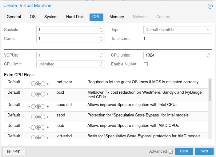
The CPU screen can be left on the defaults. If you need to increase the CPU allocation it can be done at a later stage.
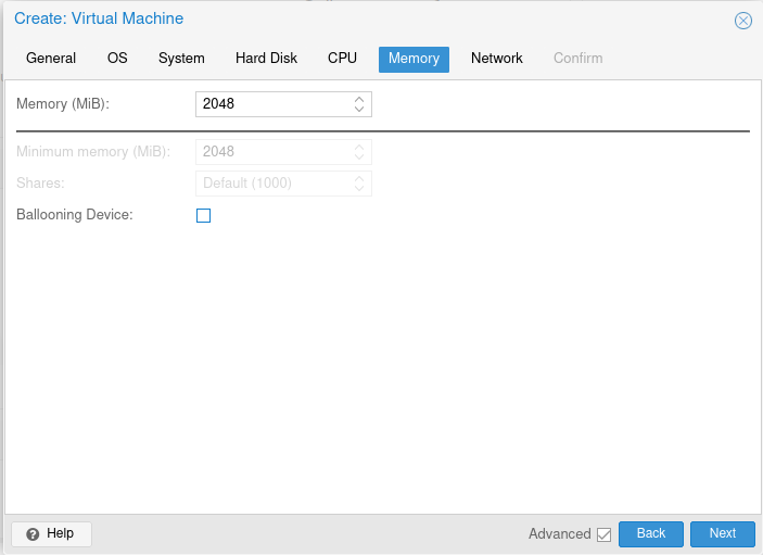
On the Memory screen, disable the Ballooning Device. The advanced checkbox at the bottom of the screen needs to be selected to show the option:
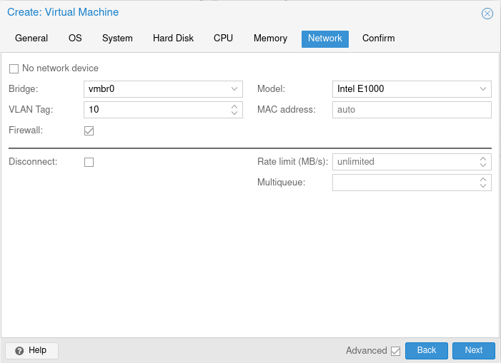
On the Network screen, set the relevant interface and VLAN tag (if required). The interface model needs to be changed from the default “VirtIO” to “Intel E1000”:
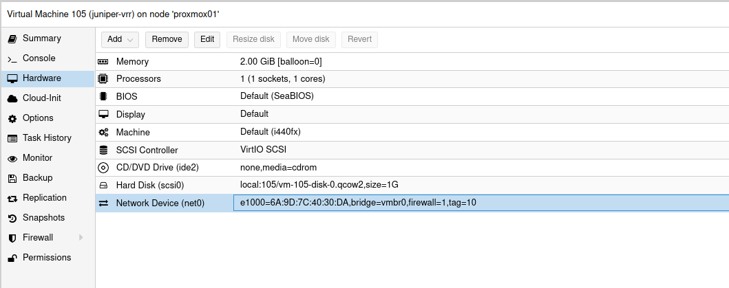
Finally finish the creation. The option to start the VM after creation should not be selected. The VM should now look like this:
VM Hardware
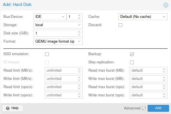
The Juniper vRR tar file contains a second disk image, metadata.img. An additional hard disk device needs to be added to the VM to make use of this. The configuration of the meta data disk is slightly different – the device type should be set to IDE instead of SCSI. As with the scsi0 disk, the storage type should be the dir storage and the disk size should be set to 1GB with the format set to QEMU image format:
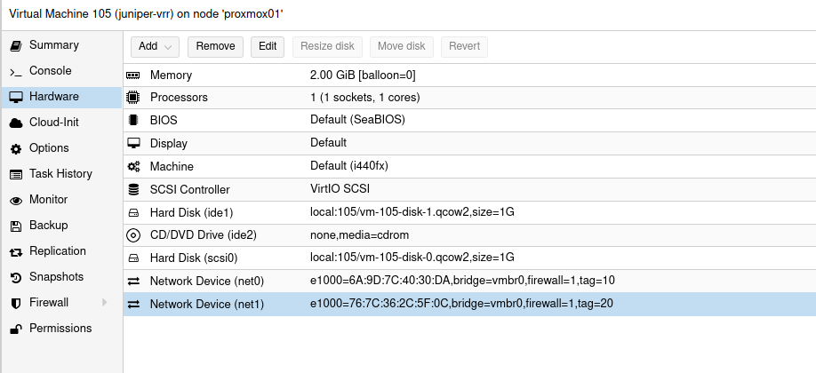
If you will be adding additional network interfaces to the VM they can be added now. The device model of these additional interfaces should be “Intel E1000” otherwise they will not work.
The completed VM configuration now looks like this for me:
Copy Images
The Juniper vRR image that you would like to run should be downloaded from the Juniper downloads site. There are multiple download options available for the vRR – select the KVM and Openstack image:

Once the download is complete, extract the archive. There is two disk images inside (in this case its from the 21.4R1 release):
junos-x86-64-21.4R1.12.img– This is the main disk which contains the OS. This image will be thescsi0device in the VM (known as disk 0).metadata.img– This is the metadata disk which will be theide1device in the VM (known as disk 1).
Get the ID of the VM (in my case it is 105) and the path to the storage directory (/var/lib/vz). There should be a images directory which contains the two disk images for the VM. Overwrite the two disk images with the ones from the archive downloaded from the Juniper site:
mv 21.4R1.12/junos-x86-64-21.4R1.12.img /var/lib/vz/images/105/vm-105-disk-0.qcow2
mv 21.4R1.12/metadata.img /var/lib/vz/images/105/vm-105-disk-1.qcow2
With the disk images overwritten, run the rescan command to update disk sizes:
qm rescan
The VM is now ready to boot. If required, you can migrate the storage to the actual storage location you want to use (eg. LVM, iSCSI or NFS).
VM Access
Start the VM and open the console. The first boot will take a while which is expected; it will reboot one or more times during this stage.
Once the VM has booted log into the console using the username root with no password. The CLI can then be started by running cli. To get SSH access to the VM, you can add skeleton config, eg.:
set system root-authentication plain-text-password
set system services ssh root-login allow
set interfaces em0 unit 0 family inet address 192.0.2.10/24
set routing-options static route 0.0.0.0/0 next-hop 192.0.2.1